

What’s the meaning of all those numbers used by yacht designers?
The terms and ratios that follow are used by all yacht designers, so it’s a good idea to have an understanding of them if you are considering buying a boat or having a custom design created. You may need to work out some of the ratios for the boats you are considering for purchase from the available information, but the formulas are simple and can be handled by an inexpensive scientific calculator. The one I use in my design business is a Sharp EL-520, almost old enough to vote, and it cost less than $25 new many, too many, years ago.
Illustrations by Ted Brewer and Mike Dickey
Basic weights and measures
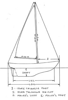
Length: Designers and builders have different ways of expressing length. Length On Deck (LOD) is the true length, omitting rail overhangs, and is the honest way to describe the length of a boat. More usually, you will see it as Length Over All (LOA), which may be the LOD if the builder is honest but often includes rail overhangs, anchor sprit, bowsprits, and even boomkins if the builder is trying to sell a “larger” boat. Length on the Waterline (LWL) is an important figure to know, as it more closely represents the usable size of the yacht than LOD or LOA, and it is a necessary figure in some of the other calculations. LWL is the length of the vessel as measured from the bow ending of the waterline to the stern ending. It should not include any rudder tip that may stick out past the aft end of the hull proper. Over the years, the LWL will increase as the yacht sinks into the water with the added weight of stores and equipment.
Beam: This is the greatest width of the hull and is often expressed as Beam (Max). Beam WL is the width at the LWL and is very useful to know but is not readily available, as a rule.
Draft: This is the depth of the hull from the waterline to the bottom of the keel or fin. Like the LWL, it will vary with the weights of fuel, water, stores, and the equipment added over the years and is usually somewhat more than the original designed or advertised draft. When you run onto a 4-foot-deep rock in a boat with 3-foot 9-inch draft, it is always nice to know that it may not be your fault.
Displacement: If you weigh the boat on a scale, that is her actual (not advertised) displacement and the weight of sea water she will displace when afloat. Most designers figure displacement when half loaded (the boat, that is, not the designer) with stores, liquids, and crew.
Displacement can be expressed in pounds, long tons, or cubic feet; one ton = 2,240 pounds = 35 cubic feet of sea water, at 64 pounds per cubic foot. Fresh water weighs only 62.4 pounds per cubic foot, so a boat taken from sea water to fresh water will sink into the water and increase her draft slightly. For example, a boat weighing 7,500 pounds will displace 117.19 cu. ft. of sea water or 120.19 cubic feet of fresh water. The difference is 3 cubic feet, so if her waterline area is 150 square feet, she will sink 3/150 of a foot (about 1/4 inch) when she is moved from salt to fresh water. This is truly insignificant for most sailors, unless you are skippering a 90,000-ton tanker.
J, I, P, E: These are letters you see on the sail plans of many modern cruiser/ racers and denote the rig dimensions. As you’ll see on the illustration on the next page, “J” is the length of the foretriangle on deck, from the mast to the headstay. “I” is the height of the foretriangle from the sheer to where the headstay intersects the mast. “P” is the main luff and “E” is the main foot. Yawls and ketches will also have Pmiz and Emiz to show mizzen dimensions.
Centers and areas
Center of Buoyancy (CB): Often called Lateral Center of Buoyancy (LCB), this is the center of the underwater volume of the vessel and can be expressed as a distance abaft the forward end of the LWL, abaft midships, or as a percentage of the LWL from the bow end. If the boat is to float on her LWL, the Center of Gravity (CG) must be in line vertically with the CB, both fore and aft and athwartship. If the two centers are not in line, the boat will change trim and so change her underwater shape, until the new CB lines up with the CG.
If your boat is floating perfectly in trim and you add 100 pounds of davits and dinghy aft, for example, you will move the center of gravity of the boat aft. The vessel will sink by the stern and the bow will come up until the underwater shape changes enough to move the CB over the new CG.
The same applies athwartship. With luck, the CB and the CG are both on the centerline of your boat, so she floats level without any heel angle. When you move to the starboard rail, you move the CG off centerline to starboard, so the boat will heel until the change in underwater shape moves the CB vertically above the new CG.
Center of Flotation (CF): The CF is the center of the waterline area and is the pivot point about which the boat changes trim, much like the pivot in the center of a teeter-totter. On normal sailing hulls, the CF is somewhat abaft the CB and, like the CB, is expressed as a percentage of the LWL, or a distance from either the bow end of the LWL, or from amidships. Of course, as the boat changes trim, due to added weight at one end or the other, the LWL shape changes, so the CF will move slightly.
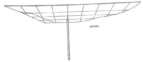
Center of Lateral Plane (CLP): Also called Center of Lateral Resistance (CLR). These indicate the center of the hull’s underwater area as viewed from the side. The CLP is readily found by tracing the outline of the underwater hull on paper, cutting it out, and balancing it on a pencil, as illustrated below. Some designers omit the rudder area when finding the CLP; others use half the rudder area.
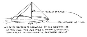
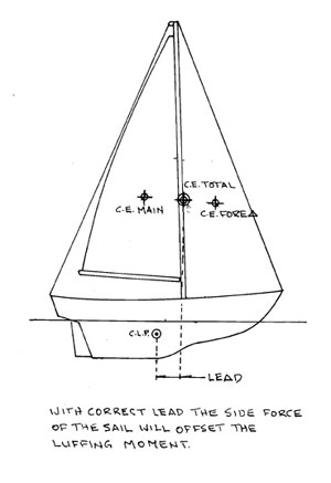
Center of Effort (CE): This is the center of the area of the sails. The CE is usually determined using 100 percent of the foretriangle area, omitting the overlap of genoa jibs. On some boats that do not carry genoas the CE may be calculated as the center of the working sails. Both the CE and the CLP may be shown on sail plans and the CE will be forward of the CLP by a distance known as lead. The lead (pronounced “leed”) is essential to provide a balanced helm and the amount of lead is based on certain characteristics of the vessel. I’ll discuss helm balance in detail in a future article and explain the need for lead.
Waterline Area: This is the area of the LWL, usually expressed in square feet. It is not always easily obtained but can be calculated roughly for a sailboat by the formula: .67 x LWL x Beam. It is more accurate if you have the Beam WL rather than the Beam (Max), of course. Knowing the LWL area is essential in working out some of the following calculations.
Seven Calculations
Fineness Coefficient (Cf): Also called the Waterplane Coefficient, or Cwp. The Cf is a figure derived from: LWL Area/(LWL x Beam WL). As shown in the illustration on page 70, the lower the Cf, the finer the hull at the waterline. Typical sailboats have a Cf of .65 to.68
Pounds Per Inch Immersion (PPI): The weight required to sink the yacht one inch. It is calculated by multiplying the LWL area by 5.333 for sea water or 5.2 for fresh water. The PPI usually increases as the hull sinks into the water as the LWL area is also increasing due to the shape of the hull above water.
Moment to Trim One Inch (MTI): The MTI is the moment, expressed in footpounds, that will change the fore-and-aft trim of the yacht one inch. For a displacement hull, the MTI is, roughly (but close enough for all practical purposes), .35 x WL Area2/Beam WL. For example, your boat has an LWL Area of 165 square feet and a Beam WL of 8 feet. Your MTI is .35 x 1652/8 = 1,191 ft-lbs, say 1,200 for rough figuring. Now you hang that 100-pound dink 18 feet abaft the CB. You have added 1,800 ft-lbs of aft moment, so your boat will trim 1800/1200 = 1.5 inches down by the stern. However, the boat does trim about its Cf and, as that is usually abaft amidships, the stern will move less than the bow. You might find that she trims 5/8 inch down by the stern, and 7/8 inch up by the bow, making a total trim change of 1.5 inches.
Wetted Surface (WS): This is the area in square feet of the underbody of the yacht, including the fin, rudder, and skeg. A boat with a large WS will have more surface friction than a boat with lesser WS and be slightly slower, given the same sail area, due to the greater resistance. This is most important in light air as, at slower speeds surface friction is the primary cause of resistance.
Speed/Length Ratio (V÷![]() L): This is the speed in knots divided by the square root of the LWL. For example, a 25-foot-waterline sailboat moving at 5.5 knots would be at a V÷
L): This is the speed in knots divided by the square root of the LWL. For example, a 25-foot-waterline sailboat moving at 5.5 knots would be at a V÷![]() L of 1.1. while a 400-foot-LWL destroyer traveling at 22 knots also has a V÷
L of 1.1. while a 400-foot-LWL destroyer traveling at 22 knots also has a V÷![]() L of 1.1. Both vessels would develop about the same resistance per ton of displacement as they are both running at the same V÷
L of 1.1. Both vessels would develop about the same resistance per ton of displacement as they are both running at the same V÷![]() L.
L.
The limiting speed for a pure displacement hull is a V÷![]() L of 1.34. Above this speed, the stern wave moves aft so that the stern loses buoyancy, the hull squats, and great additional power is necessary for a small gain in speed. In truth, the typical cruising sailboat probably averages a V÷
L of 1.34. Above this speed, the stern wave moves aft so that the stern loses buoyancy, the hull squats, and great additional power is necessary for a small gain in speed. In truth, the typical cruising sailboat probably averages a V÷![]() L of about .9 to 1.0 and only gets close to 1.3 when reaching in a stiff breeze. Tender boats may never get above 1.2 since crewmembers ease sheets when the rail buries!
L of about .9 to 1.0 and only gets close to 1.3 when reaching in a stiff breeze. Tender boats may never get above 1.2 since crewmembers ease sheets when the rail buries!
The modern beamy, super-light ocean racer can have a stern wide enough to resist squatting and the stability to stand up to a breeze, so it often achieves speeds well above 1.4, but that is semi-planing, and the boat is getting lift aft due to its speed. My BOC 60 design exceeded 20 knots at times, a V÷![]() L ratio of over 2.6, but those are very specialized yachts, definitely not good old boats!
L ratio of over 2.6, but those are very specialized yachts, definitely not good old boats!
Prismatic Coefficient (Cp): This is a figure that relates the fullness of the ends of the underwater hull to the area of the midship or largest station. The sketch below will explain it better than words can. The Cp is the percentage of the original shape that remains after the hull is carved out. The more that is cut away to “carve” the hull, the finer the ends and the lower the Cp, and vice versa.
The proper Cp for a hull depends on the intended speed and is related to the speed/length ratio V÷![]() L . The correct Cp for various V÷
L . The correct Cp for various V÷![]() L are as follows:
L are as follows:
| V÷ |
Cp |
| 1.0 and below | .525 |
| 1.1 | .54 |
| 1.2 | .58 |
| 1.3 | .62 |
| 1.4 | .64 |
Selecting the correct Cp for a sailing yacht depends on her speed which, of course, varies with the winds. For an inshore racer primarily in light-air conditions it might be wise to go to a .525 Cp, while an allround cruising yacht would benefit from a higher Cp, say .54 to.55, and an ocean racer from a yet higher Cp, perhaps .56 to.57. In any case, it is best if the Cp is a bit on the high side, since the penalty for having too high a Cp at low speeds is less serious in performance than having too low a Cp at high speeds. The high Cp should be achieved by fullness aft, not forward, as full bows have an adverse affect on performance.
Half Angle of Entrance: This is the angle, measured at the LWL, between the hull centerline and the actual waterline shape. Fine angles are desirable for good performance but can be overdone, creating a wet boat in a seaway. Angles below 19 to 20 degrees would be considered fine, 20 to 24 degrees is fairly usual for a cruising yacht, and angles of 25 degrees and above are considered bluff bows today but were fairly common in the ’60s.
Ratios for evaluating speed, comfort, and safety
Sail Area/Wetted Surface Area Ratio (SA/WS): The sail area/wetted surface area ratio is simply the sail area divided by the area of the hull that is below the LWL. It should include the keel and rudder areas. This frequently neglected ratio is the major determiner of boat speed in light and medium air. In these conditions, wave-making resistance is minimal and surface friction is the primary drag component. ratios below 2.0 indicate poor performance in light air. Ratios of 2.2 to 2.4 predict good light-air performance, while a ratio of 2.6 would indicate a boat designed specifically to sail in very light wind. Wetted surface is a difficult number to obtain, but the concept is important.
Sail Area/Displacement Ratio (SA/D): The SA/D ratio is the sail area in square feet divided by the displacement in cubic feet to the 2/3 power, or SA/D cf.666 Ratios below 14 are suited for motor sailers, from 14 to 17 for ocean cruisers and from 16 to 18 for typical coastal cruisers. Ratios over 18-20 are seen on racing dinghies, inshore racers, and ocean racing yachts. The more extreme screamers can have very high SA/D ratios indeed. My 60-foot design, Wild Thing, had a SA/D ratio, based on 100 percent foretriangle, of well over 30, depending on her displacement at the moment. Her displacement could vary widely as she could carry 8,000 pounds of water ballast in tanks on the windward side.
Displacement/Length Ratio (D/L): The D/L ratio is a non-dimensional figure derived from the displacement in tons (of 2,240 lbs) divided by .01 LWL cubed, or, Dt/(.01 LWL)3. It allows us to compare the displacement of boats of widely different LWLs. Some examples of various D/L ratios follow, but are generalities only, as there is often a wide range within each type.
| Boat type | D/L ratio |
| Light racing multihull | 40-50 |
| Ultra-light ocean racer | 60-100 |
| Very light ocean racer | 100-150 |
| Light cruiser/racer | 150-200 |
| Light cruising auxiliary | 200-250 |
| Average cruising auxiliary | 250-300 |
| Heavy cruising auxiliary | 300-350 |
| Very heavy cruising auxiliary | 350-400 |
Storm, a wonderful 27-foot LWL sloop on which I raced with Bill Luders many years ago, had a D/L ratio of 386, very heavy by today’s standards. However, Storm was 39 feet LOA, and when she heeled to a breeze her long ends would increase her sailing LWL, thus reducing her D/L ratio to a more reasonable figure when we were beating to windward. If she picked up 3 feet of WL, her D/L ratio dropped to about 281 – a significant change and one that made her a very competitive racer in the 1960s.
Capsize Screening Ratio (CSF): Some years ago, the technical committee of the Cruising Club of America came up with a simple formula to determine if a boat had bluewater capability. The formula compares beam with displacement, since excess beam contributes to capsize and heavy displacement reduces capsize vulnerability. The formula is the maximum beam divided by the cube root of the displacement in cubic feet, or B/3![]() DISPL cf. The displacement in cubic feet can be found by dividing the displacement in pounds by 64, of course.
DISPL cf. The displacement in cubic feet can be found by dividing the displacement in pounds by 64, of course.
The boat is acceptable if the result of the calculation is 2.0 or less but the lower the better. For example, a 12-meter yacht of 60,000-pound displacement and 12-foot beam will have a CSF number of 1.23, so would be considered very safe from capsize. A contemporary light displacement yacht, such as a Beneteau 311 (7,716 lb, 10-foot 7-inch beam) has a CSF number of 2.14, and a Dufour 38 (14,300 lb, 12-foot 7-inch beam) comes in at 2.07. Based on the formula, while they are fine coastal cruisers, the latter two yachts may not be the best choice for ocean passages.
Comfort Ratio (CR): This is a ratio I dreamed up, tongue-in-cheek, as a measure of motion comfort but it has been widely accepted and, indeed, does provide a reasonable comparison between yachts of similar type. It is based on the fact that the faster the motion, the more upsetting it is to the average person. Given a wave of X height, the speed of the upward motion depends on the displacement of the yacht and the amount of waterline area that is acted upon. Greater displacement, or lesser WL area, gives a slower motion and more comfort for any given sea state.
Beam does enter into it as a wider beam increases stability, increases WL area, and generates a faster reaction. The formula takes into account the displacement and the WL area, and adds a beam factor. The intention is to provide a means to compare the motion comfort of vessels of similar type and size, not to compare that of a Lightning-class sloop with that of a husky 50-foot ketch.
The CR is: Displacement in pounds/(.65 x (.7 LWL + .3 LOA) x B1.333 ). Ratios will vary from 5.0 for a light daysailer to the high 60s for a super-heavy vessel, such as a Colin Archer ketch. Moderate and successful ocean cruisers, such as the Valiant 40 and Whitby 42, will fall into the low-to-middle 30s range.
Do consider, though, that a sailing yacht heeled by a good breeze will have a much steadier motion than one bobbing up and down in light air on leftover swells from yesterday’s blow. And remember that the typical summertime coastal cruiser will rarely encounter the wind and seas that an ocean-going yacht will meet. Nor will one human stomach keep down what another stomach will handle with relish, or with mustard and pickles for that matter! It is all relative.
We’ll tackle lead and helm balance in a future article.
Article from Good Old Boat magazine, July/August 1999.


