

A 27-year-old outboard starts a newer, deeper life.
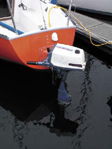
I bought Brushfire, my 1975 San Juan 24, from the Sea Scouts. Before I agreed to the deal, the Sea Scouts offered to throw in an outboard as a sweetener. The motor they dug up for me was a 7-hp Eska of 1973 vintage, a two-cycle with an integral three-quart fuel tank.
Brushfire about 3-1/2
It ran well enough once I did some research and discovered that it wanted a 24:1 fuel-to-oil ratio, but I found that even with my 180 pounds as far aft as possible and Brushfire’s scissors-style motor mount at its lowest setting, the Eska’s cavitation plate was barely below the surface. The whole prop came out of the water with any kind of wave action and the motor would race madly with a “www-AH, www-AH, www-AH,” like a hydroplane running through chop.
My original intention was to use the Eska just long enough to get miles down the Columbia River from the Sea Scouts’ base. I figured I would return it to the Scouts and treat myself to a new long-shaft Honda four-stroke. Then I started checking prices . . . and concluded that it wouldn’t be such a bad thing to have an outboard from the same era as the boat! In the course of researching long-shaft outboards on the Web, I happened upon Bay Manufacturing of Milan, Ohio, which makes shaft-length conversion kits for Mariner, Mercury, OMC, and Yamaha outboard motors, but not for 27-year-old Eskas. Looking at the pictures on their Web page caused me to wonder what it would take to do my own long-shaft conversion.
The motor
My Eska is a model 1747-C. It uses a Power Products/ Tecumseh recoil-start, two-cycle, air-cooled power head, much like a lawnmower engine’s except that the exhaust port is on the bottom of the cylinder, rather than the side. I’ve seen discussions on the Web that indicate this motor was also sold under the Sears Gamefisher and Ted Williams trademarks. It has a spring clutch to engage the driveshaft, providing neutral and drive gears. (Mine was frozen with rust, and the motor had to be started in drive. Soaking the clutch in kerosene for a week or so helped free it up.) For reverse, you swing the motor all the way around and, while hanging precariously over the transom, you try to remember which direction to twist the throttle. In drive, a small pump provides cooling water to the exhaust manifold/adapter plate that mounts the engine to the lower unit of the motor. I obtained a service manual from Certified Parts Corporation, which purchased the outboard and trolling motor divisions of Eska in 1988 and still provides most parts for these units. Some study of the exploded diagrams in the manual showed that, given the proper tools, it would be fairly straightforward to construct a shaft extension. Conve niently, the housing containing the propeller shaft, gears, and water pump separates from the main section of the column just above the cavitation plate.The cooling-water tube merely connects to the pump with a friction fit into an O-ring, while the top end of the driveshaft fits into the clutch on the engine’s output shaft in much the same way, torque being transmitted by splines. Because of this simple design, all I needed to do was add length to the cooling-water tube, fabricate a new driveshaft, and build an extension fairing, a shell that would conform to the cross-section of the column where it joined the gear housing. I decided that an additional six inches would be about right. For the best corrosion resistance and electrolytic compatibility with the rest of the motor, the new parts should have been fabricated from aluminum and stainless steel. Because I wasn’t willing to go to the trouble and expense of obtaining the ideal materials, because my MIG welder won’t handle aluminum wire reliably, and since this project was experimental anyway, I used mild-steel stock that was lying around my garage for the major components of the extension.
The long driveshaft
To avoid doing unnecessary work in case the project proved infeasible, I started with the driveshaft, the most critical piece of the extension in terms of tolerances. The original driveshaft is a 7/16-inch steel rod approximately 24 inches long, splined at each end and keyed at the lower end to drive the water pump. (I note that the original shaft will deflect the compass aboard Brushfire, so it may not be stainless steel.) What I had on hand was 1/2-inch rod, but since the center of the shaft runs free inside the column, the diameter is only critical at each end. After cutting it to length, I turned the ends of the 1/2-inch stock down to 7/16-inch. Then after fabricating a flycutter and index latch for my lathe, I cut the splines in each end of the shaft. Since I’d removed the pinion gear to disassemble the old driveshaft from the gear housing, I had it available to test the fit of my new splines. Once the splines were finished I matched the bottom end of the new driveshaft with the original, marked the locations for the snaprings that retain the pinion gear, and used the lathe to cut seats for them. The keyway for the water pump impeller is just a flat spot on the driveshaft. It was simple to rough it out with a hacksaw and an angle grinder and then to clean it up with a file.
Extending the column
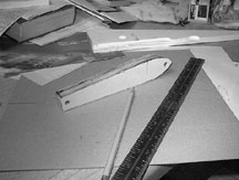
identifying the trailing edge
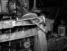
Reassured that this whole exercise might actually work, I tackled the extension fairing for the column. What I had available was 14-gauge sheet steel (approximately .075 inch thick). I quickly determined that the curve at the leading edge of the column fairs back into a straight line, so I could match it with just five sections of material as shown at right: two curved for each side of the leading edge, two straight for the trailing edges, and one flat piece for the back edge. I first obtained the outline of the required section by clamping a sheet of heavy paper between the column and gear housing and tracing around the joint. This also punched holes in the paper, providing locations for the fasteners that connect the gear housing to the column. I translated the tracing of the fairing cross section inward by the thickness of my sheet stock, then cut templates from 1/2-inch plywood. Laying the template on a flat surface, as shown in the top photo on the opposite page, showed me where the trailing edge would begin. I marked this location, then wrapped a strip of paper around the curve to the tip of the profile, marking it to establish the length of sheet metal that I would need to bend in order to form each side of the leading edge. Later on, I used the templates to align the pieces of the extension fairing while welding. Creating the curved sections for the leading edge of the fairing involved lots of hammering with the sheet metal supported against cylindrical objects of various diameters, such as an empty propane-torch tank and a length of 2-inch iron pipe. I checked my progress frequently against the plywood templates. I found that it worked best to create a curve that was tighter than what I needed, then flatten it out progressively by hammering against the anvil surface of a machinist’s vise. (It took a while to form acceptable curves, but I got there eventually.) Once I had all the pieces of the fairing worked to their proper lengths, I ground a chamfer of about 45 degrees on the outside of each edge to be joined. This was to ensure good weld penetration of the entire thickness of the sheet metal. This was important because I wanted to build up a bead that I could later grind down flush with the outside surface of the extension fairing. Assembling the pieces around my plywood templates, I tack-welded them together with a MIG welder, then removed the forms. I completed the welds a bit at a time, allowing them to cool between passes in order to minimize distortion of the sheet metal. I built each seam up into a nice, heavy bead as shown in photo.
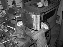
welding
Once the shell of the extension was welded together, I used an angle grinder to clean up the top and bottom edges, checking often with a framing square to make sure the surfaces were parallel with reference to the back edge of the fairing. I ground the edges until the height was uniform and slightly more than six inches, then did the final finish with a large mill file across the entire top and bottom edges of the shell to get the mating surfaces as straight and square as possible. The holes that allow water to drain from the column after the motor is hauled out were cut with a hacksaw and shaped with a file.
When I was satisfied with the fit of the shell against the gear housing and the column, I fabricated alignment tabs from 1/8-inch by 1-inch steel strap and welded them into the top and bottom of the fairing. These provide lateral rigidity as well as ensuring that the extension stays centered against the inside surfaces of the column and gear housing.
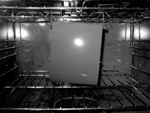
Don’t try this at home, kids, without your mom’s permission: fairing after coating and the finished result of the baking (done in a home oven).
I fabricated mounting flanges from 1/8-inch by 1-inch strap to provide the connection points at the top and bottom of the fairing. I first drilled the holes in them and then lined them up with the holes in my templates and traced the outline that would become the edges to be welded to the inside of the fairing shell. As the drawing above shows, the flanges at the rear of the fairing are threaded for the mounting bolts. Here I cheated: instead of spending a lot of time messing around with taps to thread holes in the flanges themselves (in which case they would have needed to be made of thicker material), I installed a nut and bolt on each flange, with the nut on the inside face, then I tack-welded the nuts to the flanges and removed the bolts. This provided for a strong connection in a situation in which it’s impossible to get a wrench on the nut. The bottom flange at the leading edge is constructed in much the same way, but it uses a section of threaded rod to mirror the stud on the leading edge of the column. The upper flange merely has a plain hole that the column stud passes through. It’s secured by a nut and lockwasher from inside the extension fairing. (The original trailing-edge mounting bolt was frozen; I was forced to drill it out. I elected to install its replacement from the outside of the column, otherwise both top flanges would have had plain holes.) Once the construction was complete, I ground the welds down flush with the surface of the fairing, then polished the whole outside surface with a 3M Scotch-Brite surface conditioning disc installed on an angle grinder. This is the best way I’ve found so far to remove rust and mill scale from steel components. It also left a very smooth, shiny surface, which was important for the next step. Had I been thinking ahead, I would have polished the inside surfaces of the fairing before welding it together. Since I hadn’t polished the inside, I did as much cleanup as I could afterward with wire brushes and a sand blaster. Live and learn.
Powder coating
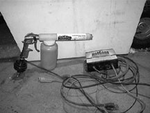
HotCoat system
Because my materials were very susceptible to rust, it was important to protect them. Epoxy-based or even enamel spray paint would probably have been adequate, although getting good coverage on the inside of the fairing would have been tricky. Luckily, I had a better alternative available. Powder coating is a process that leaves metal parts with a smooth protective layer that is harder and more durable than most paints, covers irregular surfaces more readily and uniformly, and is non-toxic to boot. The process involves applying an electrostatic charge to a finely powdered plastic that is then sprayed at low pressure over a grounded metal part. The powder sticks to the metal surfaces just like dust to a TV screen. Once it’s been coated, the part is baked in an electric oven until the plastic melts, flows, and cures to a durable covering that is resistant to abrasion and to most solvents. (The only thing I’ve found to date that will attack powder coating is methylene chloride, found in products such as spray-on gasket remover. Acetone dulls the surface slightly; gasoline and oil run right off.) This was an industrial process that required expensive equipment until a couple of years ago when The Eastwood Company started selling a hobbyist’s powder-coating package. Their basic HotCoat system sells for about $150. The nicest part of using the powder-coating process for this project was that the charged powder was attracted to and covered every surface of the fairing, inside and out, even the irregular surfaces of exposed welds. To avoid fouling the threads, I installed bolts in the threaded holes and masked off the trailing-edge stud with high-temperature fiberglass tape (also from Eastwood) before coating everything with the shade of powder I had on hand that came closest to matching the Eska’s paint. Photos on Page 12 show the fairing after coating and the finished powder-coated fairing after it was baked for 15 minutes at 400 degrees F. I also powdercoated my new driveshaft after taping off the splines and the surfaces that would bear on the bushings and seals. (Any color would have done for the driveshaft; I happened to have black in the HotCoat gun at the time.) The final piece of the project was the extension for the cooling-water tube. In this case I actually had to break down and go to the hardware store to buy aluminum tubing that matched the 3/8-inch outside diameter of the water tube, as well as vinyl hose with a 3/8-inch inside diameter to join the extension to the original tube. (Since I was there anyway, I also purchased stainless-steel cap screws, nuts, and lockwashers.) I cut the ends of the new 6-inch extension to the same angle as the end of the original water tube so they would fit together flush, then smeared the outsides of the two aluminum pieces with RTV silicone and joined them with a length of vinyl tubing as shown in photo. (Epoxy might have been a better choice for this, but so far the RTV seems to be working fine.)
Assembly is the reverse of removal
joining the cooling water tube
To reassemble the motor, I first coated all the bare metal surfaces on the bottom end of the new driveshaft with a generous layer of waterproof grease (meant for the wheel bearings of boat trailers) to protect them from rust, then reassembled the gear housing and driveshaft as shown in photo.
reassembling the gear housing and driveshaft
With the motor supported upside down on an empty 5-gallon bucket, I applied RTV silicone along the entire upper surface of the extension fairing, then fitted the extension in place and bolted it on. The trickiest part of this operation was getting the nut started on the threads of the stud inside the leading edge of the fairing. I found that a telescoping parts-retriever, a tool like a walkie-talkie antenna with a magnet at the tip, was invaluable for this. Once the nut was finally engaged with the threads of the stud, I tightened it with a socket on the end of a long extension. With the motor still upside down, I coated the bottom of the extension fairing with RTV, applied grease to the exposed metal at the top of the driveshaft, and carefully lowered the gear housing assembly onto the column until the driveshaft splines meshed with those in the clutch. Working through the exhaust port and the small gap that remained between the gear housing and the extension fairing, I used a long screwdriver to jockey the end of the water tube into location in the water pump. Once the driveshaft and water tube were started, I simply pushed the gear housing down until it was seated on the extension fairing and bolted it loosely into place. Before tightening the fasteners down for good, I put the clutch selector in the “drive” position and gave several pulls on the starting cord to make sure the driveshaft wasn’t binding and in the hope that it would tend to align itself by shifting the gear housing around slightly. The assembled result is shown on the opposite page in bottom photo. After the RTV had cured, I refilled the gear housing with SAE 90 lubricant as specified in the Eska service manual and, using the time-honored outboard-motor test stand, a sawhorse and a 55-gallon trash can full of water, fired up my motor. With the gear selector in “neutral” I was gratified to see that the clutch was now working properly. The propeller remained motionless while exhaust racketed from the relief port at the top of the column, sounding like a leafblower on steroids. Once the motor warmed up and the idle settled down, I cautiously moved the selector to “drive,” and . . . it worked!
Conclusions
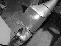
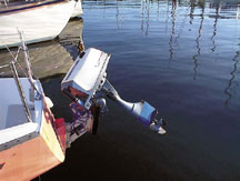
the finished project
I’ve been very pleased with this conversion’s performance aboard Brushfire. With the motor mount in its lowest position, the entire extension is underwater, giving the propeller plenty of bite, and I can move forward in the boat without it becoming a menace to low-flying birds. The tip of the gear housing’s fin is just barely in the water with the motor mount in the topmost position. With the motor rocked forward in its tilt bracket, everything is high and dry. One odd side effect of the extension is that with the motor idling and the gear selector in “neutral,” the exhaust resonates inside the comparatively thin-walled extension fairing with a funny “bloop-bloop-bloop-bloop” note that puts me in mind of The Secret Life of Walter Mitty.
If you don’t have a well-equipped metalworking facility in your garage, you should be able to find a machine shop willing to fabricate all or part of a similar shaft extension “kit.” Some research in my area turned up two shops that were capable of the job, one specializing in high-volume CNC production and not interested in one-off jobs; the other a gear-making business that estimated $225 just to make the driveshaft. Though I haven’t had to take work to a machine shop for nearly two decades, I find it hard to believe that there’s nothing left but specialists.
Fabricating the driveshaft obviously requires some moderately specialized equipment, but the operations involved are straightforward and shouldn’t be too costly in terms of labor. (It took me about six hours all told, but 80 percent of that was in building a flycutter.) If you don’t have a welding outfit, any decent machine shop should be able to construct the extension fairing as well. If you don’t know of a shop already, talking to a few old-timers around your marina should turn up someone who can do the job. Anyone who can cope with simple hand tools can handle the fabrication of the cooling-water tube extension and the final assembly. I’ve noticed that even a reconditioned long-shaft outboard starts at $900; new ones are going for $1,500 or more. If you have an older motor available, this project could be cost-effective even if you have to farm out the actual fabrication work. (Not too long ago, I noticed a 7-hp Eska identical to mine offered for $350 at my local marine exchange. Now if I were to buy that and modify it I might be able to clear about $500. Hmmm . . . )
Potential problems
Rust:
While I hadn’t noticed any signs of rust on the exterior of the extension assembly, it still concerned me that the whole thing is potentially susceptible to corrosion. I’m relieved to report that, after four months and about four-and-a-half hours of accumulated running time (including two extended motor-only runs of an hour each), there was no sign of a problem when I disassembled the extension to take photos for this article. Brushfire sails in fresh water. I would definitely go to the expense of using inherently corrosion-resistant materials for saltwater operation, or if the motor were semi-permanently installed in an outboard well.
Sealing:
The through-the-prop exhaust system depends on a good seal between the mating surfaces of the column, the extension fairing, and the gear housing. The walls of the column casting are about 1/8-inch thick, and the sealing surface of the gear housing is a nice milled area that varies from 1/4-inch to about 1/2-inch wide. The walls of the extension fairing are roughly 1/16-inch thick, providing only minimal sealing area. Almost immediately after I put the converted motor into service I noticed bubbles of exhaust gases forcing their way between these junctions. The RTV silicone obviously wasn’t enough. I later made gaskets from 1/32-inch automotive-gasket material and bedded them in hardening-type gasket sealer. These worked for a while, but they eventually started leaking also.
I’ve since welded lengths of 1/8-inch steel rod along the inside of the extension fairing at the top and bottom, making a generous bead that I ground down flat to provide a wider sealing surface. I also filed the powder coat off the mating surfaces. I suspect that the coating is so slick that the sealants I’ve tried have not been able to adhere to it very well. I have yet to put enough run-time on the motor to tell whether this change will be effective.
Drain holes:
When I originally designed and built the extension, I neglected to do anything about the original drain slots at the bottom of the column’s leading edge. These slots are right at the waterline, and when I first tried the converted motor aboard Brushfire I noticed quite a bit of exhaust escaping from them. My remedy wasn’t pretty, but it does work: I threaded stainless-steel sheet metal screws into two scraps of wood about 1/8-inch thick and, with the extension fairing removed, filled the drain slots with thickened epoxy, using the wood on the inside of the column as backing. I tightened the screws down to hold the wooden backing blocks in place while the epoxy cured, then filed everything down flush with the mating surface of the column. With the extension reassembled, the epoxy seals the original drain holes. (The screw heads are visible in the bottom photo on the opposite page, just above the top of the extension fairing at the leading edge of the column.)
Shaft alignment and vibration:
I have no way to evaluate this, since there’s so much incidental vibration when the motor’s running. I’m reasonably confident that the drive shaft itself is true, since I could check that while I was machining it; I don’t know how accurately it is aligned between the motor and gear housing but there’s not a lot that I can think of to correct such a problem. (I try to ignore the possibility, apart from making sure I have fresh batteries in my hand-held VHF transceiver in case the gear housing should fall off in mid-river and I need to call for a tow.)
Resources
Bay Manufacturing
P.O. Box 1250
Milan, OH 44846
419-499-4602
Certified
Parts Corporation
1111 W. Racine Street
P.O. Box 8468
Janesville, WI 53547-8468
608-752-9441
orders 800-356-0777
The
Eastwood Company
263 Shoemaker Road
Pottstown, PA 19464
800-345-1178
Sea Scouts Ship 601
Article taken from Good Old Boat magazine: Volume 4, Number 4, July/August 2001.


