

Tips on how to extract the old one and install the new one.
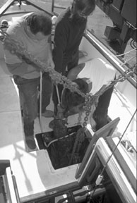
Preparing to hoist out the old power plant.
In the September/October issue of Good Old Boat, we discussed the decisions to be made when the inevitable day comes that your power plant needs to be either rebuilt or replaced (Repowering, Part 1: The decisions). In either case, the engine will have to be removed from the boat. Once you have decided that engine replacement is the way to go, and you have made the decisions laid out in the previous article, the actual engine replacement can begin.
Although the photographs and text detail the specific procedures on our schooner, Delphinus, most of the problems we encountered generally apply to all sailboats. We were replacing a 1980 saltwater-cooled Volvo MD-11C diesel that had a left-hand prop with a new 2001 freshwater-cooled Yanmar diesel designed for a right-hand prop. Whether the propeller is left-hand (counter-clockwise) or right-hand (clockwise), is determined by the direction the propeller turns, as viewed from the stern, when the transmission is in “forward.” (Usually, the crankshaft of the engine itself turns in the opposite direction from the propeller shaft). Although the Yanmar that I decided to use has slightly greater horsepower than the old engine, its physical dimensions – height, length, and width, as well as weight – are all less than that of the old Volvo. This is common with replacement diesels, due to improved diesel design within the last couple of decades.
The old diesel is lifted out using the marina’s Travelift.
Before the old engine can be removed, all of its connections to the boat must be taken off: the exhaust, water lines, fuel line, control cables, and electrical connections. After everything connecting the old engine to the boat has been disconnected, the screws or bolts holding the engine mounts to the beds can be removed, and the engine is ready to be hoisted out of the hull.
Difficult removal
It would be nice to think that the old engine can be easily removed. In point of fact, in fiberglass boats, the engine was often installed before either the deck mold and/or the interior mold were put in place – a bizarre construction concept. As a result, some engines have to be removed through the cabin, while others can be taken out through a removable cockpit panel. Our boat has a removable cockpit panel, since the centerboard trunk, on which the schooner-rig’s mainmast rests, is just forward of the engine compartment doors and eliminates this possibility.
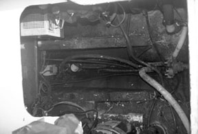
After the messy disassembly of all the connections to the old diesel, the dirty engine compartment is ready for a good scrub before work begins on the beds for the new engine.
Sometimes an engine can be removed more easily in sections, such as by first removing the transmission, and sometimes the old engine can only be removed by lifting it out by one end. Often, discouragingly, the only way is by cutting out a section of fiberglass. The same problem may hold true for wooden boats, where major woodworking reconstruction is sometimes necessary to get the old engine out of its cocoon.

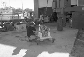
I do a mock-up of the engine-bed alignment procedure on the deck of our home.
In order to take out our old engine, a section of the interior aft countertop in the cabin had to be cut away. In addition, the Volvo engine and its transmission were longer than the cockpit hatch opening, and the old engine had to be canted at a 45-degree angle to get it out of the hull. I had planned to remove the old Volvo’s transmission, which would reduce the overall length and make getting the engine out much easier. However, in trying to do this, I discovered one of the four bolts holding the transmission to the engine was frozen in place. Its head was stripped, and nothing I could do would free it. I probably could have drilled it free, but its location, underneath the transmission in a nearly inaccessible spot, made this almost impossible.
Yard expertise
When it’s time to remove the old engine, the obvious choice is between doing it yourself or having the marina do it. Most boatyards have done this job many times before and have the equipment and expertise to do it efficiently. If you are hoisting the engine out yourself, it goes without saying that you must make sure your hoist can handle the weight. For an engine that has to be removed through the cabin, special equipment, which most marinas have, is necessary.
With the old engine gone, the engine compartment can now be cleaned up of old oil and grease. Although there are many good (and expensive) marine degreasing products available, you might want to consider using Dawn dishwashing soap, which does the job as well as or better than anything else. It’s also great for cleaning up greasy hands and is biodegradable. Once the engine compartment has been cleaned and becomes more habitable, the old wiring, plumbing, and exhaust system can be removed and/or reconfigured for the new engine.
Although our installation was done in the spring of 2002, we purchased our new engine in the fall of 2001. This was done for two reasons: first, we purchased it just before a 5-percent price increase; second, having the engine on hand for several months before the installation was to begin enabled us to check its dimensions, measure the sizes of the water hoses, exhaust hose, fuel hose, fuel-return line, and water-heater heat-exchanger hoses, and purchase the necessary hose diameters and lengths with the assurance they would all fit when the time came for the hook-ups.
New propeller
Our old Volvo diesel had a left-hand prop, but our new Yanmar has a right-hand rotation, so early on we bought a new right-hand propeller (a good thing, since there was a six- to eight-week delivery schedule). We also needed a new, longer prop shaft, due to the shorter length of the Yanmar, as well as a flange coupling for that shaft that would be compatible with the flange on the transmission of the Yanmar. It’s probable that the flange coupling on your old shaft (as with ours) will be rusted and frozen in place so it cannot be removed by sliding it back out of the hull. Fortunately, once the old engine is out of the way, the old prop shaft and its coupling can be easily removed by sliding it forward, out into the empty engine compartment. The chances are that the rubber hose on your shaft-log hasn’t been replaced in a long time, so now’s a good time. Better yet, consider a dripless coupling, which is easily installed once the old rubber hose and packing gland have been removed. (I installed a packless shaft seal manufactured by PYI, Inc.). This investment will pay dividends in the future by eliminating the awkward contortions required when readjusting the packing nuts, as well as providing a dry bilge.
With the old engine out of the way, this was the perfect time for easy removal of the old water heater (long overdue), which was in the engine compartment, and the installation of a new one. The new Raritan water heater, with engine-water heat exchanger and 120-volt immersion heater, was of similar size to the old Raritan whose steel case was rusting away. The new Raritan heaters now have plastic cases and more insulation.
New engine bed
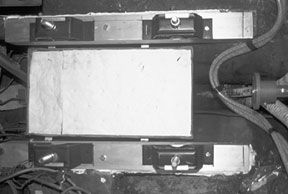
A new engine bed is established, using 3/8-inch-thick, 3-inch by 3-inch marine-grade aluminum angle. A new oil drip-pan has been constructed of fiberglass, with an Oil-Zorb insert, and the level and alignment of the new beds is checked before they are fastened in place.
Since it’s probable that your new engine will be smaller than the old one, the engine bed will have to be rebuilt. This may mean tearing out the old stringers and installing new ones. If you have a fiberglass boat, the new beds will have to be built up using fiberglass and epoxy. If you’re not well acquainted with fiberglass work, it’s probably a good idea to leave this job to a professional.
Engine mounts are placed in position and bolted down.
We were fortunate that the mounting width of our new Yanmar was exactly 3/4-inch less than that of the old Volvo. So we used two heavy-duty, 3/8-inch thick, 3-inch by 3-inch marine-grade aluminum angles bedded in 3M 5200 and through-bolted to the old fiberglass-and-oak bed. These heavy-duty aluminum beds ensured that when the mounts were installed they would be true and level.
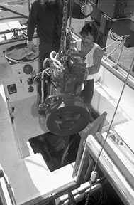
The new Yanmar engine is uncrated in preparation for installation.
In nearly all engine conversions, the different size of the new engine and the rebuilt engine beds will probably mean that the old oil-drip pan will no longer fit and a new one will have to be made. I constructed the new one out of fiberglass and lined it with a replaceable sheet of Oil-Zorb.
The Travelift brings in the new engine.
Most auxiliary engines are installed on mounts that have heavy-duty rubber shock absorbers between the top threaded stud that is bolted to the engine, and the base, which is bolted to the engine-bed. Usually there are four mounts, near each corner of the engine. The mounts use nuts and washers on the studs, which are used to adjust the engine up and down and lock it in place. (The bottom nut that actually supports the engine is called the “jack nut.”) The bases of these mounts have holes for the mounting bolts, and one of the two holes is slotted. These slots allow the engine to be moved sideways slightly so it can be lined up perfectly with the propeller-shaft coupling.
Different mounts
When preparing to install the engine mounts, be aware that for many auxiliary engines the engine mounts are different for the front and rear of the engine or for the port and starboard sides due to the different weight and dynamic loads imposed on them. These shock-absorbing mounts usually have a number molded into their rubber, which indicates the rubber’s hardness. For engines that require different mounts fore-and-aft or side-to-side, the installation manual will specify their required locations. During the installation, and in the future, keep oil from getting on the rubber sections of these mounts, since it can cause the rubber to deform and swell, eventually resulting in incorrect engine-to-shaft alignment.
Shaft alignment
If you are installing a new engine and retaining your old through-hull shaft log, the engine-coupling flange will have to be lined up perfectly with the flange on the propeller shaft. The engine bed must be horizontal athwartships, with an inclination angle within the allowable limits of the engine-mount adjusting nuts. Most manufacturers’ installation manuals give detailed descriptions on this alignment procedure, which usually is one of two types or a combination of both.
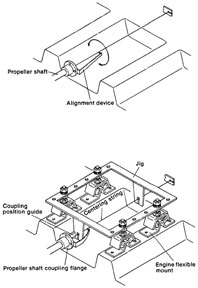
To determine the centerline of the propeller shaft, its height, and its inclination, a pointer is bolted to the propeller-shaft flange, with a string coming out at shaft-center. This string has a fish-weight tied on the free end, and this weight goes over a piece of wood that is temporarily clamped to some point farther forward. When the propeller shaft is rotated, this free-end piece of wood is moved until the pointer circles the string evenly. The position of this string now becomes the centerline extension of the propeller shaft, from which engine-bed construction and engine placement measurements can be made. Installation instructions recommend that this pointer and string be fastened directly to the propeller-shaft flange, rather than to an intervening flexible coupling or “Drive-Saver,” which could introduce an error.
Although the construction of a new engine bed and alignment of the new engine can be done directly from measurements to this centerline string, a much easier and less time-consuming way of creating the new engine bed and aligning the engine is through the use of an engine-bed alignment jig. These jigs can sometimes be rented from an engine distributor for your particular engine, greatly simplifying the engine-mount placement measurements. As in the previous step, the string from the center of the propeller shaft passes through alignment holes in the jig, and the engine mounts, which are bolted onto the jig, can be located perfectly on the new engine bed, with the assurance that the propeller shaft flange and the engine transmission’s flange will match very closely when the new engine is installed.
Check tolerances
Once the engine mounts have been fixed to the new bed and the engine has been installed, it’s time to check the coupling tolerances between the two flanges. Mismatches between the two surfaces (the flange on the engine and the flange on the propeller shaft), should be compensated for by adjusting the motor mounts, which can move the engine up or down an inch or more. The slots in the engine mounts also allow you to move the front or rear of the engine to one side or the other to match up the two flanges. Using a feeler gauge around the periphery between the two flanges, you can adjust the engine mounts so that the two flanges mate to within 1/1,000 inch. Note that these tolerances should be checked between the flanges themselves, and not with an intervening flexible-coupler or “Drive-Saver.” Once the two flanges match perfectly, the flexible coupling can be added, and, with everything lined up, the bolts on the flanges are tightened. This shaft alignment is vital for preventing Cutless-bearing wear, transmission damage, and vibration.
A new engine installation is usually performed on land. It’s important to realize that when a shaft alignment is done on land, the alignment can change after the boat is back in the water with the mast stepped and the rigging tensioned. On a new engine, this alignment can also change during the first few days or weeks as the rubber in the new engine mounts compresses to its final size. Some installation manuals suggest that the jack nuts on the engine mounts be raised one turn above perfect alignment to compensate for this inevitable rubber compression.
Anti-siphon valves
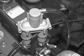
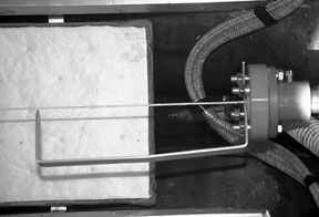
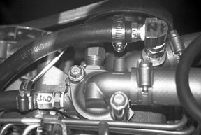
An anti-siphon valve is installed in the raw-water output line, above. Note that this Vetus valve has an overflow tube going into the bilge, so drops of salt water don’t fall on the engine. Below, since the engine fittings that connect to the hoses feeding the hot-water tank’s heat exchanger were not available from Yanmar, these brass adapters, purchased from Maryland Metric, provide the interface between the engine’s British standard pipe threads and U.S. standard pipe fittings.
If the raw-water output from the engine that goes into the exhaust-mixing elbow is below or close to the boat’s waterline (when level or heeled over), it’s imperative that an anti-siphon valve be added. Without this valve, after the engine is turned off, water can continue to siphon into the exhaust system, eventually backing up into the engine itself and causing major damage. The anti-siphon valve allows air to enter the system when there is a suction, which occurs during siphoning, but the air valve closes when pressure is present, as when the engine is running.
There are many types of anti-siphon valves, made from various materials. Some have connections for a small tube that allows the few drops of overflow water to go directly to the bilge rather than drop on top of the engine. This can prevent fresh water or corrosive salt water from attacking the top of your new engine. This overflow tube has another advantage: by blowing into the tube you can determine whether your siphon-vent is clogged or stuck.
Engine connections
A pointer is attached to the propeller-shaft flange, and a string comes through a hole in this pointer at the center of the propeller shaft. The shaft is then rotated, and the free end of the centering string is moved until the pointer rotates around the string evenly through 360 degrees. This establishes an extension of the centerline of the propeller shaft, from which the new engine-bed can be created. The engine alignment jig allows the installer to fasten the engine mounts to the jig. The jig can then be aligned with the propeller-shaft string. The fore-and-aft position of the engine can also be determined by the jig’s position in relation to the propeller-shaft flange. If a flexible coupling or Drive-Saver will be used, its width must be included before the engine mounts can be bolted down to the engine bed. (Illustrations courtesy of Yanmar)
When the engine is in place, it’s time to connect the fuel supply line, fuel return line(s), water system, exhaust system, electrical system, and control cables. If hoses, control cables, and wiring in the engine compartment haven’t been changed in a while, now is a good time.
When it comes to determining sizes of fittings and machine screws on your new engine, you must realize that there are three primary measuring systems in use around the world, metric standards, USA (inch) standards, and British (inch) standards. As the world moves toward metric standards, sailboat power plants will be increasingly built to these standards.
Fortunately there are now many places in the United States that can supply metric tools and machine screws. But even on an engine built to metric standards, there are anomalies. Strangely, most countries that use metric standards, both in Europe and in Asia, use the British (inch) standard for measuring pipe fittings. I discovered this contradiction when installing my metric system Yanmar engine. Almost everything on this engine is metric, but the threads on the engine for the water fittings that feed the heat-exchanger for the on-board hot water tank are British (inch) standard.
British standard pipe-fittings come with either a cylindrical (parallel) thread or with a tapered thread. My Yanmar engine demanded a fitting with British standard tapered threads (which are designated in Japan, and in the Yanmar shop manual as “PT.” Thus, a designation of “PT-3/8” (as shown in the shop manual) means that the fitting is a British standard 3/8-inch tapered pipe fitting.
No fittings
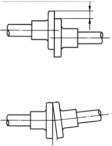
When a mismatch between the engine’s transmission flange and the propeller-shaft flange is as illustrated, the engine must be raised or lowered by adjusting the jack nuts on all four engine mounts. A mismatch such as this between the two flanges indicates that the engine’s centerline is not parallel with the propeller shaft’s centerline. In this case, one end of the engine must be raised or lowered.
The Yanmar engine has two plugs that can be removed to accept the hose-fittings for the hot-water tank’s heat exchanger. Although Yanmar sells the hose adapters that fit these threads, the fittings had been on back order for several months and were not available when I was installing my new engine. Luckily, I discovered Maryland Metrics on the Internet. This company sells a wide range of metric tools and fittings as well as British standard and American standard pipe fittings and adapters. They had adapters in stock that went from the British standard tapered 3/8-inch pipe thread (PT-3/8) on the Yanmar to a U.S. standard 3/8-inch pipe-thread, which solved the problem nicely. Once I had converted to the U.S. thread, elbows and hose adapters were readily available.
Incidentally, Maryland Metrics has a wonderful website describing the threads in all three systems. They also have a huge inventory of nuts, bolts, parts, adapters, and metric tools. For my very small order for two adapter fittings, they couldn’t have been nicer or more cooperative in helping me solve my problem.
Final preparations
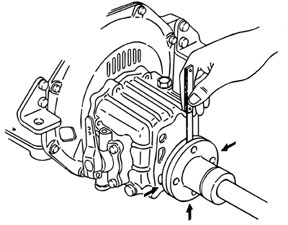
A final check, using a feeler gauge around the circumference of the two flanges, assures that these flanges meet accurately. (Illustrations courtesy of Yanmar)
When everything has been completed, it’s time to fill the crankcase and the transmission with the oils specified by the manufacturer. Before doing this, however, check the oil levels, since many manufacturers supply the new engine with oil already in the crankcase and transmission. This is an especially important check with diesel engines, since too much oil in the crankcase can cause a runaway engine. With freshwater-cooled engines, fill the engine’s heat-exchanger with a 50/50 solution of water and anti-freeze, as per the manufacturer’s instructions. Many manufacturers recommend that the water used with the anti-freeze be distilled water, since there’s no telling what chemicals might be in city water.
For diesel engines it now will be necessary to bleed the fuel system, otherwise the engine won’t start. This bleeding is usually done at two places in the fuel supply system as well as at the injectors of each cylinder. These locations will vary from manufacturer to manufacturer and will be described in the owner’s manual. Once you have located these points it’s a good idea to paint all of these bleed-points with white paint. It will make it a lot easier to locate them at some time in the future when you accidentally run out of fuel and you have to do a bleeding job under less than ideal conditions. It will also make it easier to bleed the system each time you change the engine’s fuel filter.
Check liquid levels
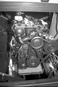
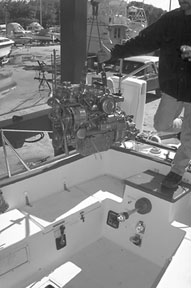
The new engine, as seen from inside the cabin, looking aft through the engine access doors.
After the engine is run for its first test – no more than a couple of minutes – the levels of oil in the crankcase and transmission, as well as the cooling-water level, must be checked. As the fluids are distributed throughout the engine and heat exchanger, levels can drop.
Most diesel manufacturers recommend that if your engine hasn’t been used in a few days, it’s a good idea to pre-lubricate it before starting. For engines that have a manual Stop control, this can be done by holding out the Stop control while turning the engine over with the starter for about five to 10 seconds. If the engine hasn’t been used in a really long time, wait 30 seconds and repeat the procedure. This will distribute oil throughout the engine. It’s also a good idea, after starting, to let the engine run at mid-range for about five to 10 minutes before putting it under load.
When stopping, let the engine cool down by idling it for about five to 10 minutes, then, just before stopping the engine, give it a burst of power to blow out any carbon in the cylinders.
When our boat was finally back in the water after the new engine had been installed, I was hoping that it would be a calm day for the one-hour motor-trip from the marina to our home dock, but this was not to be. When I came out of the marina I had 20 knots of wind right on the nose and a high chop. It was literally a shake-down cruise. But the new installation performed flawlessly, and I was able to head home at hull speed.
This new engine installation should be good for the next 25 to 30 years. I just wish that I could be good for that long.
Article taken from Good Old Boat magazine: Volume 5, Number 6, November/December 2002.


